Search filter
134 results found
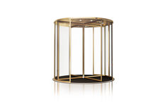
Revo.PRIME manual
… Manual revolving door system with low canopy height and narrow profile system for three- or four-leaf doors
TSA 325 NT Manual
… Manual revolving door system for three- or four-leaf doors
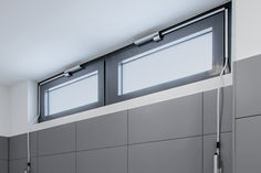
Manual fanlight openers
… manual fanlight openers provide fresh air. Thus, natural ventilation is simple and effective, also with closed main windows. Fanlight windows make rooms brighter.

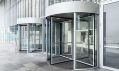
Manual revolving doors
… Manual revolving doors ensure quiet, elegant and simple access to your building. They provide a needs-based solution when visitor numbers and passage clearances are in the lower range.
Manual trigger switch
… manual release of hold-open systems

TSA 355 Manual door
… Manual revolving door system for three- or four-leaf doors
TSA 355 Manual door
… manual revolving door system TSA 355 Manual really comes into its own.

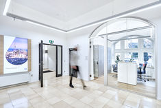
Movable glass partitioning walls
… Manual sliding wall systems offer you "mobile" flexibility for room partitioning. To open the glass partition walls, the glass elements are simply pushed together and elegantly stacked on the side.
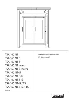
TSA 160 NT user manual
… User manual TSA 160 NT Contents … For the user … Symbols and illustrations Warning notices Warning notices are used in these instructions to warn you of property damage and personal injury. XX Always read and observe these warning notices. XX Observe all measures marked with the warning symbol and warning word . Warning symbol Warning word Meaning Danger to persons. CAUTION Non-compliance can result in minor to medium injuries. Further symbols and illustrations Important information and technical notes are highlighted to explain correct operation. Symbol Meaning means “important note”; information about avoiding property damage means “additional Information” The user's attention should be drawn to important addition information. There is no danger to persons or property, but it is particularly useful to read the additional information carefully. XX … Special cases In certain cases, deviations from the information given in this user manual may occur. Examples: àà special wiring àà special function settings (parameters) àà special software XX Please contact the service technician responsible for further information. … Explanation The side of the door where the hinges from which the door leaf is suspended are located. Usually that side of the door located in the opening direction. The side of the door facing the hinge side. Usually that side of the door located in the direction of closing movement. The active leaf of a double-leaf door. When the door is used, the active leaf must open as the first door leaf and close as the last door leaf. The secondary leaf of a double-leaf door. When the door is used, the passive leaf may not open until the active leaf has left the closing position and must close again as the first door leaf. Push button, switch or movement detector for activating the door drive. The activation device is located within the room enclosed by the door. Activation function in the modes of operation AUTOMATIC and EXIT ONLY 1). The activation device does not have any function in the NIGHT/OFF mode of operation. Push button, switch or movement detector for activating the door drive. The activation device is located outside the room enclosed by the door. Activation function in the AUTOMATIC mode of operation. The activation device does not have any function in the EXIT ONLY 1) and NIGHT/OFF modes of operation. Access control function (for example key switch or card reader) used by authorised persons to activate the door drive. The control function is active in the AUTOMATIC, EXIT ONLY1) and NIGHT/OFF modes of operation. Push button for opening and closing the door. Control function only in the AUTOMATIC and EXIT ONLY modes of operation1). The door is opened automatically when the button is first pressed and closed again automatically when the button is pressed the second time. The function can be activated during commissioning by parameter setting. When the door is pressed manually out of the closing position during an activated closing position inhibition, the door opens automatically as soon as a specific adjustable opening angle is exceeded. Presence detector (e.g. active infrared light switch) for protecting the swinging range of the door in the opening direction. As a rule the sensor is located on the hinge side of the door on the door leaf. Presence detector (for example active infrared light switch) for protecting the swinging range of the door in the closing direction. As a rule the sensor is located on the opposite hinge side of the door leaf. Self-locking switch with which immediate stopping of the door drive can be triggered in case of danger. The door drive remains in its current position until the user unlocks the stop switch again, thus terminating the stop situation. Electrical closing sequence control In normal operation of double-leaf door drives, the closing sequence of the door leaves is controlled by the control units of the door drives, with the passive leaf being closed first. The active leaf remains in the open position until the hold-open time of the passive leaf has expired. Only then does the active leaf begin to close. Integrated closing sequence control (-IS): In the event of a power failure for 2-leaf door systems, the closing sequence is controlled mechanically with TSA 160 NT-F-IS. The door leaves are closed by means of the power storage of the drives, with the active leaf being kept open by the integrated mechanical closing sequence control unit at approximately 30° opening angle before the closing position is reached. When the passive leaf has reached the closing position, it releases the active leaf by means of the mechanical elements of the integrated closing sequence control so that it can also close completely.. The EXIT ONLY mode of operation can only be selected with the optional mechanical programme switch. TSA 160 NT Introduction Term Explanation Electric strike Fail-secure electric strike Available as AC or DC electric strike version. When the door drive is activated, the electric strike is switched on by the control unit of the door drive provided the door is in the closing position. The electric strike remains activated until the door has left the closing position. Fail-safe electric strike DC electric strike version. The electric strike is switched off when the door drive is activated provided the door is in the closing position. The electric strike remains switched off until the door has left the closing position. The bar feedback function is a contact integrated in the door catch that is activated when the door is locked mechanically by the tie bolt of the door lock. It signals to the control unit that the door is locked mechanically and can therefore not be opened by the door drive. In this case the control unit ignores the control commands of all the activation devices. Push button for restarting the drive after the operating voltage has been switched on or after a fire alarm has been terminated. When the push button is pressed, the self-retention integrated in the drive is activated, causing the drive to be activated. When the door is closed in a de-energised state, the door leaf is impeded by the lock latch of the electric strike. To make sure the door can pass the lock latch safely during closing, an integrated limit switch is activated in the drive once a specific opening angle has been reached, reducing the braking strength. The door accelerates and closes into the lock at increased speed. In an energised state, this function is regulated by the drive control unit. Bar feedback Reset Latching function … For the user TSA 160 NT Carefully read and abide by this user manual before commissioning the door. Always observe the following safety instructions: àà Operating, maintenance and repair conditions specified by GEZE must be observed. àà The commissioning, mandatory installation, maintenance and repair work must be performed by experts authorised by GEZE. àà The connection to the mains voltage must be made by a professional electrician. àà No changes may be made to the system without prior agreement from GEZE. àà GEZE shall assume no liability for damage caused by unauthorised changes to the system. àà The owner is responsible for safe operation of the system. àà Have a service technician check the safe operation of the system at regular intervals. àà Should safety devices be misaligned, thus preventing them from fulfilling their intended purpose, further operation is not permissible. The service technician must be informed without delay. àà Make sure that the safety stickers are attached visibly to any glass leaves and are in a legible state. àà Protect the programme switch against unauthorised access. àà Danger of injury by sharp edges on the drive when removing the cover àà Danger of injury by parts hanging down àà This appliance can be used by children aged from … years and above and persons with reduced physical, sensory or mental capabilities or lack of experience and knowledge if they have been given supervision or instruction concerning use of the appliance in a safe way and understand the hazards involved. àà Children shall not play with the appliance. àà Cleaning and user maintenance shall not be made by children without supervision. … 10 *) Door drive Link arm or roller guide rail Smoke switch control unit *) Activation device outside (KA) (optional) Activation device authorised (KB) (optional) Smoke switch *) Activation device inside (KI) (optional) Programme switch (optional) Lockable mechanical program switch (MPS-ST) for releasing the programme switch Stop switch (optional) 11 12 13 14 15 16 17 18 19 20 CLOSE DOOR manual trigger switch *) Electric strike (on site) Door handle with door lock (on site) Inside building Outside building Closing safety sensor (SIS) (optional) Door transmission cable (optional) Opening safety sensor (SIO) (optional) Internal programme switch Reset switch (F-reset) (TSA 160 NT F only) optional, in connection with TSA 160 NT F
(PDF | 411 KB)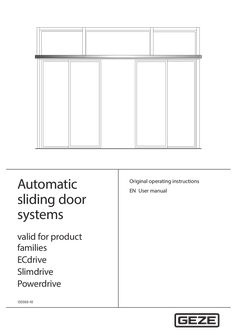
User manual Automatic sliding doors
… User manual DCU1-NT, DCU1-2M-NT, DCU1, DCU1-2M Contents … For the user … Symbols and illustrations Warning notices Warning notices are used in these instructions to warn you of personal injury and property damage. XX Always read and observe these warning notices. XX Observe all the measures that are marked with the warning symbol and warning word . Warning symbol Warning word Meaning WARNING Danger to persons. Non-compliance may result in death or serious injuries. CAUTION Danger to persons. Non-compliance can result in minor to medium injuries. Further symbols and illustrations Important information and technical notes are highlighted to explain correct operation. Symbol Meaning means “important note”; information about avoiding property damage means “additional Information” The user's attention should be drawn to important addition information. There is no danger to persons or property, but it is particularly useful to read the additional information carefully. XX Symbol for an action: This means you have to do something. XX If there are several actions to be taken, keep to the given order. Escape and rescue route; means the sliding door cannot be operated in escape and rescue routes Not an escape and rescue route; means the sliding door cannot be operated in escape and rescue routes BO … BO Break-out; means BOthat the door leaves and side panels are equipped with a break-out function BO No break-out; means the function is not possible for break-out doors Product liability In accordance with the manufacturer's liability for their products as defined in the German “Produkthaftungsgesetz” (Product Liability Act), the information contained in this user manual (product information and proper use, misuse, product performance, product maintenance, obligations to provide information and instructions) is to be noted and followed. Failure to comply releases the manufacturer from his statutory liability. … Special cases In certain cases, deviations from the information given in this user manual may occur. Examples: àà Special wiring àà Special function settings (parameters) àà Special software XX Please contact the service technician responsible for further information. … Terms Term Activation device inside (KI) Explanation Push button, switch or movement detector for activating the door drive. The activation device is located within the room enclosed by the door. Activation function in the “Automatic” and “Exit only” modes of operation. The activation device does not have any function in the “Night/Locked” and “Off” mode of operation. Activation device outside (KA) Push button, switch or movement detector for activating the door drive. The activation device is located outside the room enclosed by the door. Activation function in the “Automatic” mode of operation. The activation device does not have any function in the “Exit only”, “Night/Locked” and “Off” mode of operation. Activation device authorised Access control function (for example key switch or card reader) used by authorised (KB) persons to activate the door drive. The activation function is active in the “Automatic” “Exit only”, “Night/Locked” and “Off” modes of operation. Opening safety sensor (SIO) Presence detector (e.g. active infrared light sensor) for protecting the swinging range of the door in the opening direction. The sensor secures the secondary closing edge. Closing safety sensor (SIS) Presence detector (e.g. active infrared light sensor) for protecting the swinging range of the door in the closing direction. The sensor secures the main closing edge on the inside and outside. Emergency stop Self-locking switch with which immediate stopping of the door drive can be triggered in case of danger. The door drive remains in its current position until the user releases the emergency stop switch again, thus terminating the emergency stop situation. Emergency lock When the emergency lock is triggered, the door is closed and locked. The activations and safety devices are deactivated during the closing process. Reset Push button for restarting the drive after the operating voltage has been switched on or after a fire alarm has been terminated. When the push button is pressed, the self-retention integrated in the drive is activated, causing the drive to be activated. … For the user Fundamental safety precautions Carefully read and abide by this user manual before commissioning the door. Always observe the following safety instructions: àà Operating, maintenance and repair conditions specified by GEZE must be observed. àà The commissioning, mandatory installation, maintenance and repair work must be performed by experts authorised by GEZE. àà Any relevant additional country-specific and European directives must also be observed. àà Use in dry rooms only. àà The intervals for safety-related testing are to be complied with based on the country-specific regulations. àà The connection to the mains voltage must be made by a professional electrician. àà No changes may be made to the system without prior agreement from GEZE. àà GEZE shall assume no liability for damage caused by unauthorised changes to the system. àà The owner is responsible for safe operation of the system. àà Have a service technician check the safe operation of the system at regular intervals. àà Should safety devices be misaligned, thus preventing them from fulfilling their intended purpose, further operation is not permissible. The service technician must be informed without delay. àà Make sure that the safety stickers are attached visibly to any glass leaves and are in a legible state. àà Protect the programme switch against unauthorised access. àà Danger of injury by sharp edges on the drive when removing the cover àà Danger of injury by parts hanging down àà This appliance can be used by children aged from … years and above and persons with reduced physical, sensory or mental capabilities or lack of experience and knowledge if they have been given supervision or instruction concerning use of the appliance in a safe way and understand the hazards involved. àà Children shall not play with the appliance. àà Cleaning and user maintenance shall not be made by children without supervision. … .1 Standard functions (automatic mode of operation) In normal operation, the door is automatically opened and closed. What happens? An activation device (push button, switch or movement detector) is triggered. What does the door do? Door opens and closes again. Closing safety sensor is triggered when the door is open. Door remains open. Closing safety sensor is triggered when the door is closed. Door remains closed. Closing safety sensor is triggered while the door is closing. Door opens again. Opening safety sensor is triggered when the door is closed. Door remains closed. Opening safety sensor is triggered while door is opening. Door stops. Opening safety sensor is triggered while door is opening. The door does not stop until the reduced opening width (escape route width) has been reached. A person moves toward the opened door and a movement detector is Door remains open. activated. A person moves toward the closing door and a movement detector is Door opens again. activated. Door contacts an obstruction when opening. Door contacts an obstruction when closing. BO BO Door stops, waits and attempts to move to the open position at a reduced speed three times. Then the door closes again. Door reopens immediately, waits the hold-open time and then closes at a reduced speed. Door leaf or side panel is broken out. Door remains in the current position and can be moved manually. Door leaf or side panel is latched in again. Door functions again in the last mode of operation. BO BO 11 Description … Explanation A fault 07 (fire alarm) is displayed at the programme switch. Door closes immediately with dampened closing speed and remains closed. Changing the mode of operation is not possible. Door can only be opened manually. Normal operation is restored by pressing the reset switch. The reset switch can be reached by opening the drive cover. See Chapter 5, No mains voltage. Behaviour at smoke alarm (Slimdrive SL-RD) Operating status Smoke alarm Normal operation Mains power failure … DCU1-NT, DCU1-2M-NT, DCU1, DCU1-2M Locking/unlocking if there is no mains voltage Locking type Toothed belt locking Measures Locking only makes sense when the door is closed. Locking with drives with built-in rechargeable battery àà If the door is to be locked and this door is the only point of access: XX Push the door closed manually from the inside. XX Push the locking pin. XX Activate the (inner) authorised activation device until initialisation of the drive is completed. DPS or TPS indicates Night/Locked mode of operation. Door opens – leave the building – door closes – locks again and switches off. Unlocking from the outside with drives with built-in rechargeable battery XX Activate the (outer) authorised activation device until the drive is initialised and the door starts to open. Door opens – door closes – locks again and switches off. Unlocking from the inside with drives with built-in rechargeable battery: XX Activate the (outer) authorised activation device until the drive is initialised and the door starts to open. Door opens – door closes – locks again and switches off. Unlocking with drives without built-in rechargeable battery (only possible from the inside) XX Push the door to the desired locking position and push/slide the locking pin (9, Chapter … ). The door leaves are unlocked and can be opened manually. Rod locking, Lock A and folding door lock Locking is only possible when the door is closed. Locking with drives with built-in rechargeable battery If the door is to be locked and this door is the only point of access: XX Push the door closed manually from the inside. For sliding door with rod locking: XX Lock using an Allen key through the drill hole in the cover in the indicated direction of rotation. For sliding doors with Lock A (see also installation instructions “Automatic hook bolt lock Lock A”): Manual locking: XX Insert a tool with approx. Ø … mm at the bottom into the slot of the main closing edge/side screen profile and press the lock upwards. Manual unlocking: XX Insert a tool with approx. Ø … mm at the bottom or top of the slot in the main closing edge/side screen profile and lock in the indicated direction of movement. With folding door and folding door locking: XX Unlock with a hollow set-screw through the recess in the left post profile in the indicated direction of rotation until the door leaves can be pushed opened by hand. Locking for SL-BO Locking is only possible at a closed door. Locking with drives with built-in rechargeable battery If the door is to be locked and this door is the only point of access: XX Push the door closed manually from the inside. XX Push the locking pin. XX Activate the (inner) authorised activation device until initialisation of the drive is completed. DPS or TPS indicates Night/Locked mode of operation. Door opens – leave the building – door closes – door locks again and switches off. Unlocking from the outside with drives with built-in rechargeable battery XX Activate the (outer) authorised activation device until the drive is initialised and the door starts to open. Door opens – door closes – door locks again and switches off. Unlocking from the inside with drives with built-in rechargeable battery XX Activate the (inner) authorised activation device until initialisation of the drive is completed. Unlocking with drives without built-in rechargeable battery (only possible from the inside) XX Push the door to the desired locking position and push the locking pin (9, Chapter … ). The door leaves are unlocked and can be opened manually. After the mains voltage has been restored, the (locked) door automatically switches to the “Night/Locked” mode of operation. 19 Fault messages DCU1-NT, DCU1-2M-NT, DCU1, DCU1-2M … , Behaviour at fire alarm Door does not unlock or lock Locking defective Door does not close Closing safety sensor (SIS) interrupted or misaligned Obstruction in travel path Unlock/lock the door manually: XX Check lock in the “Night/Locked” mode of operation. If the locking is defective: XX Notify a service technician. XX Clean the closing safety sensor (SIS). XX Check settings of light curtain. XX Remove obstruction and check door leaf for ease of movement. XX Check movement detector. Movement detector triggers constantly XX Select a different mode of operation. “Hold open”, “Off” mode of operation No mains voltage (e.g. power failure) See Chapter 5, No mains voltage. Programme switch cannot be operated Programme switch is blocked Programme switch is defective Fault messages displayed Fault in the door system at programme switch Activate key switch. Enter password. XX Request servicing. See Chapter 6, Fault messages XX XX Carry out a reset/delete the fault memory àà With keypad programme switch: XX Use key or to change to the mode of operation “Off” (see Chapter
(PDF | 2 MB)